Ericsson SPR1100 Operations Instructions
Browse online or download Operations Instructions for Recording Equipment Ericsson SPR1100. Ericsson SPR1100 Operating instructions User Manual
- Page / 300
- Table of contents
- BOOKMARKS
- SPR1100 Stream Processor 1
- Revision History 4
- Trademarks 4
- Warnings, Cautions and Notes 5
- EMC Compliance 5
- Contact Information 6
- 1 Introduction 9
- 1.1 Introduction 11
- Marketing Code Price Object 13
- Supply Object 13
- Description 13
- Introduction 15
- 1.3 Summary of Features 22
- MPEG-4 HD MPEG-4 HD 25
- MPEG-4 SD 25
- MPEG-4 SD different bit rate 25
- 1.3.2 Audio Processing 26
- 1.3.3 Data PIDs 28
- 1.3.4 Service Components 29
- 1.3.5 PID Processing 29
- 1.3.6 Table Processing 30
- 1.3.7 Transport Streams 30
- 1.3.8 Redundancy 30
- 1.3.9 SPR1100 and nCC 31
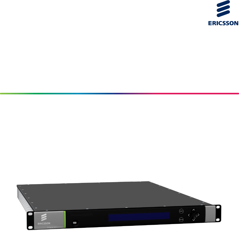
- 1.4 Front Panel 32
- 1.5 Base Units 33
- 1.6 Rear Panels 34
- 2 Installing the Equipment 37
- 2.1 Read This First! 39
- 2.2 Preliminary Checks 40
- 2.3.2 Ventilation 41
- Cautions! 42
- Warnings! 42
- 2.5 AC Supply Operation 43
- 2.5.2 AC Power Supply Cord 44
- 2.6 DC Power Operation 45
- 2.8 Signal Connections 48
- Installing the Equipment 49
- 3 Getting Started 51
- 3.1 Introduction 53
- Getting Started 55
- Services 62
- 3.17 How to Monitor Alarms 71
- 4 Front Panel Control 73
- 4.1 Introduction 75
- 4.2.3 LCD 76
- 4.3 Front Panel Menus 77
- 4.3.1 Top-Level Menu 78
- 4.3.2 System Menu 78
- 4.3.4 System > Alarms 79
- 4.3.5 System > Versions 80
- 4.3.6 System > HW Config 80
- Front Panel Control 81
- 5 Web GUI Control 83
- 5.1.1 Title Bar 88
- 5.1.4 About Button 88
- 5.1.5 Tabs 89
- 5.1.6 Navigation Path 89
- 5.1.8 Web Pages 90
- 5.1.10 Results Frame 91
- 5.2 Status 93
- 5.3 Alarms 95
- 5.3.2 Alarms > History 96
- 5.3.3 Alarms > Set Mask 96
- 5.4 Configure 98
- 5.4.3 Configure > System 99
- Web GUI Control 101
- 2/1553-FGC 101 1400 Uen B 101
- 5.5 Versions 163
- 5.5.2 Versions > Details 165
- 5.6 Support 167
- Chapter 6 171
- Contents 171
- 6.1.3 MPEG Layer 176
- 6.1.4 RTP Layer 176
- 6.1.5 UDP Layer 177
- 6.1.6 IP Layer 177
- 6.1.7 Ethernet Layer 177
- 6.1.8 IP Overhead 177
- 6.2.1 Overview 178
- 6.2.2 Services 180
- 6.2.4 Audio Output 182
- 6.2.5 Transport Packets 182
- 6.3 SPR1100 Redundancy 183
- 6.4 IP Interface Redundancy 184
- 6.4.3 Same Network Mode 186
- 6.5 Device Redundancy 188
- 6.6.1 System Architecture 192
- 6.6.2 Ethernet Interfaces 193
- 6.6.3 Multicast Routing 193
- 6.6.4 Forwarding Capacity 193
- 6.6.5 IGMP Snooping 193
- 6.6.7 MGP 194
- Port TCP/UDP Description 195
- 6.7 Temperature Monitoring 196
- 6.7.3 Fans 197
- 6.8.1 Real Time Clock 197
- 6.9.1 Supported Protocols 198
- 6.9.2 Operation 198
- 6.10 XPO 199
- 6.11 Clock & Timing 199
- Chapter 7 201
- 7.1 Introduction 203
- (SPR/HWO/MPM1) 203
- 7.2.1 Inputs and Outputs 204
- 7.2.2 Loss of Video Input 204
- 7.2.3 Output Bit Rate 204
- 7.2.5 Transport Packets 204
- Caution! 205
- Warning! 205
- 7.4 Obtaining New Licenses 209
- 7.6 Installing a Patch File 211
- Chapter 8 213
- 8.1 Introduction 215
- 8.2 Preventive Maintenance 215
- 8.3 Maintenance and Support 216
- 8.4 Alarms 217
- 8.5 Fault-finding 218
- 8.5.5 Cannot Access Web GUI 222
- 8.6 SNMP Traps 225
- 8.6.2 Using SNMP Traps 226
- 8.7 Viewing Log Files 227
- A Glossary 231
- B Technical Specification 251
- B.2.1 Overview 253
- B.2.2 IP Parameters 254
- B.2.3 MAC Address 254
- B.3.1 Overview 254
- B.3.2 Data Port Parameters 255
- B.3.3 IP Parameters 255
- B.3.4 MAC Address 255
- B.4.1 Overview 255
- B.4.2 Video Formats 256
- Item Specification 257
- B.5 Environmental 258
- B.6 Power Supply 259
- B.7 Compliance 260
- B.7.2 EMC 261
- B.7.3 Telecommunications 261
- B.7.4 CE Marking 261
- B.7.5 C-Tick Mark 262
- B.7.6 Packaging Statement 262
- B.7.7 Packaging Markings 262
- Technical Specification 263
- FGC 101 1400 Uen B 263
- B.7.9 Equipment Disposal 264
- B.7.10 Lithium Batteries 264
- B.7.11 Recycling 265
- C Audio Coding Standards 267
- C.1.1 MPEG 269
- C.1.2 MPEG-1 Layer I/II 269
- C.1.3 Dolby Digital 269
- C.1.5 Dolby E 270
- D Dolby Metadata Presets 271
- D.1 Dolby Metadata Presets 273
- Selected Option Description 274
- E Alarm Lists 275
- E.1 Alarms 277
- Operation Effect 278
- Annex F 289
- F.1 Overview 291
- F.1.2 Corrective Measures 292
- F.2 Operation 293
- F.2.2 Configuration 294
- Automatic Loudness Control 295
- F.3 The Audio Pipeline 297
- F.4 Standards Compliance 298
- F.4.4 Further Information 299
Summary of Contents
SPR1100 Stream Processor Software Version 6.7.x (and later) REFERENCE GUIDE 2/1553-FGC 101 1400 Uen B
Introduction 2/1553-FGC 101 1400 Uen B 1-2 1.3.5 PID Processing ...
Web GUI Control Figure 5.20 Configure > System Web Page 5.4.3.1 Configure > System > Slots To view and configure the modules fitted in
Web GUI Control 5.4.3.1.1 Configure > System > Slots > Slot 1 > MPM1 To view and edit the parameters of the module located in slot 1
Web GUI Control To view and edit current settings, select the Alarm Masks button from MPM1 > Video web page. Figure 5.24 Video > Alarm Mask
Web GUI Control Figure 5.26 Audio Module > Alarms Web Page This page gives a detailed list of all the alarms that may occur on the MPM Audio
Web GUI Control Configure > System > Slots > Slot 1 > MPM1 > Audio Module > Dolby Metadata Presets > Dolby Metadata Presets 1
Web GUI Control Bitstream Mode – A drop-down menu enabling the selection of the bitstream mode. Line Mode Compression Profile – A drop-dow
Web GUI Control Mixing Level – A drop-down menu specifying the mixing level. Room type – Enables you to select the room and monitor type.
Web GUI Control A/D Converter Type – A drop-down menu specifying the analog-to-digital conversion method used. Digital Re-emphasis – A dr
Web GUI Control The only user-editable field on this page is as follows: Check duplicate IP Address – If this facility is enabled, the unit wil
Web GUI Control Autorevert Delay – Selects autorevert delay, 0 – 255 seconds. The time taken to enable an interface to participate in redundan
Introduction 1.1 Introduction 1.1.1 Who Should Use this Reference Guide This Reference Guide is written for operators / users of the Ericsson SPR110
Web GUI Control Figure 5.31 Control Interface Group > Physical Control Port 2 5.4.3.2.2 Configure > System > Network Configure > Dat
Web GUI Control Figure 5.32 Network Configure > Data Interface Group 1-2 See Section 5.4.3.2.1 for details of user-editable fields. 5.4.3.2.3
Web GUI Control Active/Active, Same Network Figure 5.34 shows the web page settings for active-active, same network mode. Figure 5.34 Active-Acti
Web GUI Control Figure 5.35 Active-Active, Different Network: Data Interface Group 3-4 5.4.3.2.4 Configure > System > Network Configure &
Web GUI Control Figure 5.36 Network Alarm Configuration Web Page This page displays a list of network alarms that are currently configured and al
Web GUI Control Figure 5.38 Option Slots Status > Option Monitor Alarms Web Page The column showing the Severity of the alarm comprises a dro
Web GUI Control Card Status – Indicates whether module has booted or not. Card Mode – Indicates the module mode. S-Number – Indicates the
Web GUI Control Figure 5.40 System > Base Unit Web Page The following fields, not all of which are user editable, are available from this pag
Web GUI Control The Fan Speed Status fields give information on the current speed of each of the 5 configured fans, in revolutions per minute (rpm
Web GUI Control Figure 5.42 Base Unit > Advanced Web Page The following fields are displayed on this web page: Chip Id – Describes the pat
Introduction Audio Leveling Control: enables operators to comply with national legislation mandating audio leveling control on services. 1.1.4
Web GUI Control Figure 5.43 Base Unit > Build Version Web Page The following read-only fields are available on this page: Host Controller C
Web GUI Control Figure 5.44 Base Unit > Alarms Web Page The column showing the Severity of the alarm comprises a drop down menu (similar to t
Web GUI Control Figure 5.45 System > Standalone 1+1 Redundancy Web Page The following fields are available on this page: Device Role – Role
Web GUI Control Status – Current unit status. Active indicates that all the unit’s data outputs are enabled while Passive indicates that they
Web GUI Control Figure 5.47 System > IP Input Redundancy Switching Parameters > Web Page 5.4.3.7 Configure > System > MGP support To
Web GUI Control Figure 5.49 MGP Support > MGP Group Web Page The following fields are available from this web page: MSM Multicast Address
Web GUI Control 5.4.3.8 Configure > System > SNMP To view and edit the SNMP Parameters, select the SNMP parameters from the System web page
Web GUI Control Config Trap Wait – The minimum time (in seconds) between each config change message sent. Config Event Index – The referenc
Web GUI Control Figure 5.53 Input Pane Transport Streams are grouped by Physical Interface. Each Transport Stream is defined by its IP address an
Web GUI Control 5.4.4.1.1 Input Pane Action Menu The Input pane Action button provides menu options for managing the content of the Input pane,
Introduction Marketing Code Price Object Number Supply Object Number Description SPR/SWO/SDMP2 FAZ 101 0161/16 FAT 102 0834 SPR license 1 SD MPEG-2
Web GUI Control Figure 5.55 Outputs Pane Output services are again grouped by Physical Interface. Output services are created by dragging acros
Web GUI Control Figure 5.56 Output Pane Action Menu Add transport stream – Enables a new transport stream to be created and added to the outp
Web GUI Control Video Component Note: If the video is within a Reflex Group, this pane will be called Video Reflex Component. Video PIP Co
Web GUI Control Figure 5.58 Properties Window Showing Tabbed Levels 5.4.4.3.1 Properties Action Menu This menu is relevant only when a data int
Web GUI Control Delete Selected – Deletes the selected item. Make Selected As Secondary – Forces the selected unit to be the slave or Second
Web GUI Control Figure 5.61 Import Transport Streams Pop-Up Window 5.4.4.3.3 Properties > Transport Stream (Output) To see details of a Tran
Web GUI Control The following fields are available (not all of these parameters will always be present, nor will they all be user-editable): Ou
Web GUI Control Note: In active-active, different network mode (see section 5.4.3.2.3), you must set separate setting for the data 4 interface in
Web GUI Control The following fields are available (not all of these parameters will always be present, nor will they all be user-editable): Pr
Web GUI Control DVB Mode PMT Stream Type – Displays the type of Program Map Table Stream in Digital Video Broadcast mode. ATSC Mode PMT Str
Introduction Marketing Code Price Object Number Supply Object Number Description SPR/UPG/SWO/SD2/SD4 FAZ 101 0161/37 FAT 102 0847 SPR upgrade l
Web GUI Control Un-checking this box allows you to set a specific group rate. If you know your pass-through components are higher than the above a
Web GUI Control The following fields are available (not all of these parameters will always be present, nor will they all be user-editable): P
Web GUI Control Figure 5.68 Properties > Video Component > Input Tab The following fields are available: Video X Alarms – This pane deta
Web GUI Control Properties > Video Component > Format Conversion To view and edit the format conversion properties, select the Format Conve
Web GUI Control Figure 5.70 Properties > Video Component > Encode Tab (Reflex) The following fields are available (not all of these paramet
Web GUI Control Properties > Video Component > Output To view and edit the video component output properties, select the Output tab from th
Web GUI Control Figure 5.72 Properties > Video Component > Component Pane There is only one field available: PID – Packet identifier of
Web GUI Control Figure 5.73 Properties > Audio Component > Input Tab The following fields are available: Input Format– Name of the curr
Web GUI Control Bad RC Packets – Internal status information only. Delay – Shows the current delay through the unit. Properties > Audio C
Web GUI Control HE-AAC – High efficiency AAC encode (AAC with Spectral Band Replication). Requires one SPR/SWO/AUD/AAC license for each stereo
Introduction Marketing Code Price Object Number Supply Object Number Description SPR11/CHASSIS/1AC/RAA FAZ 101 0161/66 2x KDU 137 733/1 SPR1100 Act
Web GUI Control Figure 5.75 Properties > Audio Component > Encode Tab > Automatic Loudness Control The following fields are displayed:
Web GUI Control To display the alarm settings, select the Alarms tab from the Audio Component accordion. Figure 5.76 Properties > Audio Compo
Web GUI Control Figure 5.77 Properties > Audio Component > Component Tab The following field is displayed: PID – PID of the audio Compon
Web GUI Control Figure 5.78 Properties > Audio Component > Duplicate Component Accordion 5.4.4.4 Modules Pane The column pane on the righ
Web GUI Control Figure 5.79 Modules Pane 5.4.4.4.1 Modules > Card Modules By expanding the Card Modules icon at the top of the pane, the Medi
Web GUI Control 5.4.4.4.2 Modules Action Menu The Modules pane Action button provides menu options for managing the content of the Modules pane.
Web GUI Control 5.4.4.4.4 Modules > Services This pane enables you to see which services are allocated, available or potentially available. To
Web GUI Control Figure 5.85 Information Pane 5.4.4.5.1 Warnings Warnings are listed here when you make changes to a configuration and attempt t
Web GUI Control Figure 5.87 Information – Errors 5.4.4.5.3 Changes Changes are listed here when you modify the configuration in the Input, Outpu
Web GUI Control Figure 5.89 Information – Changes Highlighted 5.4.5 Configure > Config Report When the unit has been configured, the current
Introduction Marketing Code Price Object Number Supply Object Number Description SPR/SWO/PIP/R FAZ 101 0161/25 2x FAT 102 0835 SPR Redundant Pa
Web GUI Control The initial view shows each component of each service. The report indicates all known data about the component, and also to which
Web GUI Control 5.4.6 Configure > Save-Load To view this page, select the Save-Load tab from the main Configure page. Figure 5.92 Configure
Web GUI Control 5.4.6.2 Restore Standard Configuration from File This feature enables the configurations stored as an XML file to be uploaded to
Web GUI Control Figure 5.96 Configure > Licenses See Chapter 7, Options, Licensing and Upgrades for further instructions on obtaining and ins
Web GUI Control Figure 5.97 Version > Build Web Page The web page displays the Actual and Expected build version numbers for the different sof
Web GUI Control 5.5.2 Versions > Details To view the detail of the software components select the Details tab from the Versions top-level tab
Web GUI Control 5.5.3 Versions > Hardware To view information about the hardware components select the Hardware tab from the Versions top-leve
Web GUI Control 5.6 Support Various logs may be retrieved via xml files and may be viewed from the Support tab. Further tabs can be selected fro
Web GUI Control The following ‘main’ log files may be retrieved by right-clicking on the relevant link and selecting ‘Save target As’, Save Link t
Web GUI Control Figure 5.101 Support > System Files Web Page The following system files may be retrieved by right-clicking on the relevant li
Introduction Marketing Code Price Object Number Supply Object Number Description SPR/UPG/SWO/AUD/AC3DEC/R FAZ 101 0161/84 2x FAT 102 1607 SPR Redund
Web GUI Control 2/1553-FGC 101 1400 Uen B 5-88 BLANK
6 Stream Processing and Networking Chapter 6 Contents 6.1 Introduction to Transport Streams...
Stream Processing and Networking 6.4.1 Control Network Redundancy ... 6-146.4.1.1 Auto
Stream Processing and Networking Figure 6.6 Interface Addressing – Active/Active Port Mode ...6-17Figure 6.7 Interface
Stream Processing and Networking 2/1553-FGC 101 1400 Uen B 6-4 BLANK
Stream Processing and Networking 6.1 Introduction to Transport Streams 6.1.1 IP Encapsulation of MPEG Transport Streams An MPEG Transport Stream has
Stream Processing and Networking Figure 6.2 Mapping of MPEG-2 TS Packets 6.1.3 MPEG Layer The MPEG-2/DVB layer is specified in ISO/IEC IS 13818
Stream Processing and Networking 6.1.5 UDP Layer The UDP layer is according to RFC768 User Datagram Protocol. The user can control the target UDP por
Stream Processing and Networking Table 6.1 IP Overhead Item Overhead factor Comments MPEG-2 TS 1.0 UDP 1324/1316 = 1.006 UDP header=8 bytes
Stream Processing and Networking Parameter Value Description Off [Default] IP Output is disabled Output Enable On IP Output is enabled if the IP dest
Introduction 1.2 SPR1100 Systems Overview The Ericsson SPR1100 is a high-density-broadcast video processor for operators to launch additional tel
Stream Processing and Networking 6.2.2 Services The system is capable of forming up to 72 services divided between the output transport streams.
Stream Processing and Networking 6.2.3 Coded Elementary Stream The compressed output streams from the module are in the form of MPEG-2 transport pack
Stream Processing and Networking 6.2.4 Audio Output 6.2.4.1 Transcoding The Audio Transcoder supports transcoding at 48 kHz only. The audio outp
Stream Processing and Networking 6.2.5.2 Transport Packet Headers PIDs used in the transport packet headers are configurable and have valid continuit
Stream Processing and Networking network failure, the SPR1100 can be configured to gather its data from a different input source; this can be the
Stream Processing and Networking If both control ports have a link up, and Control Port Selection is set to Automatic Redundant, the primary port will
Stream Processing and Networking 6.4.3 Same Network Mode In a Same Network Mode (also known as a Same Subnet Mode), both interfaces are connected
Stream Processing and Networking Figure 6.6 Interface Addressing – Active/Active Port Mode Active/Active interfaces maintain a virtual MAC and virtu
Stream Processing and Networking 6.4.6.1 Automatic Failover Automatic failover is available in Active/Standby Port Mode. If the active interface
Stream Processing and Networking Terminology Primary The main unit within a 1 + 1 Redundancy group. This unit is normally expected to be Active (broa
Introduction Figure 1.1 SPR1100 Channel Tiering 1.2.1.2 Application #2: Disaster Recovery Many operators run disaster recovery sites in case some
Stream Processing and Networking indicate that the configuration of the 2 units could not be synchronized automatically. If both of the units
Stream Processing and Networking 6.5.3.4 Manual Controls There are a number of manual controls available. These allow configurations to be copied bet
Stream Processing and Networking 6.6 A Typical SPR1100 Redundant System 6.6.1 System Architecture Figure 6.9 shows the Ericsson peripheral compo
Stream Processing and Networking - Device redundancy - Standalone 1+1 redundancy, transparent addressing in redundancy. Multicast Guard Protocol (MGP
Stream Processing and Networking Switches must be capable of running an IGMP Querier. Typically the IGMP Querier will be the VLAN with the lowest
Stream Processing and Networking Table 6.5 Common TCP/UDP Port Numbers Port TCP/UDP Description 21 TCP ftp for device upgrades 23 TCP telnet for
Stream Processing and Networking Figure 6.10 Ingress and Egress of SPR 6.7 Temperature Monitoring Temperatures are reported to the user in degre
Stream Processing and Networking 6.7.3 Fans The fans fitted to the chassis are speed controllable, and are a user configurable parameter fan speed co
Stream Processing and Networking The user can enter the IP address of the SNTP server to be used, the default address is 000.000.000.000, which in
Stream Processing and Networking Parameter Description message. The options are: Start Messages Only, i.e. only system start up events. Fail and Start
SPR1100 Stream Processor ENGLISH (UK) - READ THIS FIRST! If you do not understand the contents of this manual. DO NOT OPERATE THIS EQUIPMENT. A
Introduction The SPR1100 is therefore ideal for such services, because it is a very space-efficient solution to providing parallel encoding of TV
Stream Processing and Networking 2/1553-FGC 101 1400 Uen B 6-30 BLANK
Options, Licensing and Upgrades Chapter 7 Contents 7.1 Introduction...
Options, Licensing and Upgrades 2/1553-FGC 101 1400 Uen B 7-2 BLANK
Options, Licensing and Upgrades 7.1 Introduction This chapter describes the options that may be used with the Ericsson SPR1100 Stream Processor, and
Options, Licensing and Upgrades 7.2.1 Inputs and Outputs The MPM1 has no external inputs or outputs. All data is passed into and out of the modul
Options, Licensing and Upgrades 7.3.1 Handling Modules Caution! Care must be taken to when inserting or withdrawing modules to avoid damage to unders
Options, Licensing and Upgrades Handle modules carefully, holding it by its edges or its rear panel. Do not touch solder joints, pins, or ex
Options, Licensing and Upgrades 7.3.4 Removing a Module Caution! To avoid damaging the module, always handle carefully (see section 7.3.1) and avoid
Options, Licensing and Upgrades Figure 7.3 Modules Pane - Reallocation 2. Change the exclusion settings for the module by selecting the module
Options, Licensing and Upgrades 7.4 Obtaining New Licenses The functionality of the SPR1100 depends on the hardware options fitted and the software o
Introduction Figure 1.3 SPR1100 Standalone System A large number of services can be processed in a single unit. With the addition of a backup unit y
Options, Licensing and Upgrades Figure 7.5 Finding the Host Card Chip ID for License Generation The unique Chip ID of the option card to en
Options, Licensing and Upgrades 7.4.4 Entering License Keys The keys are saved in an XML (e.g. newlicensedetail.xml) ready to be entered onto the uni
Options, Licensing and Upgrades 2/1553-FGC 101 1400 Uen B 7-12 3. From the web GUI, open the Configure > Save-Load page (See Chapter 5,
Preventive Maintenance and Fault-finding Chapter 8 Contents 8.1 Introduction...
Preventive Maintenance and Fault-finding 2/1553-FGC 101 1400 Uen B 8-2 List of Figures Figure 8.1 Current Alarm List ...
Preventive Maintenance and Fault-finding 8.1 Introduction This chapter details the schedules and instructions, where applicable, for routine inspecti
Preventive Maintenance and Fault-finding When the power supply cord or plug is damaged. If liquid has been spilled, or objects have fallen i
Preventive Maintenance and Fault-finding For systems support you can choose either Gold Business Critical support or Silver Business Advantage. These
Preventive Maintenance and Fault-finding Table 8.1 Alarm Levels Alarm Color Description Masked Green Any change of state of the alarm is logged,
Preventive Maintenance and Fault-finding Warning! Do not remove the covers of this equipment. Hazardous voltages are present within this equipment and
Introduction 1.3 Summary of Features 1.3.1 Video Processing 1.3.1.1 License Enabled Resolutions Software licenses and upgrade options are avail
Preventive Maintenance and Fault-finding 8.5.3 Power Supply Problems/Unit Not Working If the unit Status LED is unlit, fault-find the problem as
Preventive Maintenance and Fault-finding 1. Ensure the power is turned off and the power cable is disconnected from the AC power inlet(s). 2. Ease o
Preventive Maintenance and Fault-finding Table 8.3 Fans Not Working/Overheating Step Action If Result of Action is Yes… If Result of Action is
Preventive Maintenance and Fault-finding Table 8.5 Control Ports Alarms Alarm Description Ctrl x: Link Down No link has been established on this Et
Preventive Maintenance and Fault-finding Step Action If Result of Action is Yes… If Result of Action is No… 3 Check network switch operation. I
Preventive Maintenance and Fault-finding Loss of audio (from any source) Loss of VBI data Invalid Parameter (indicating which area video/audi
Preventive Maintenance and Fault-finding When the SNMP trap is received, the management station displays it and the manager can choose to take an
Preventive Maintenance and Fault-finding 8.6.2.1 Supported Protocols SNMP versions 1, 2c and 3 are supported, primarily for alarm trap handling. The
Preventive Maintenance and Fault-finding To access the logs: 1. From the web GUI, select the Support > View Logs web page. This page provide s
Preventive Maintenance and Fault-finding There is a lot of information you can give us that will enable us to diagnose your problem swiftly. When cont
Introduction Table 1.9 SPR1100 NSTC Transcoding Permutations Outputs Any Res 1080i 720p SD 1080PsF PIP INPUT NSTC i30 i25 1920 i30 1440 i30 128
Preventive Maintenance and Fault-finding 2/1553-FGC 101 1400 Uen B 8-18 BLANK
A Glossary Annex A The following list covers most of the abbreviations, acronyms and terms as used in Ericsson Manuals, User and Reference Guides.
Glossary AMOL I and II Automatic Measure of Line-ups I and II: Used by automated equipment to measure programme-viewing ratings. ARP Address Re
Glossary Bouquet A collection of services (TV, radio, and data, or any combination of the three) grouped and sold together, and identified in the SI
Glossary Chrominance The color part of a TV picture signal, relating to the hue and saturation but not to the luminance (brightness) of the signa
Glossary DCE Data Communications Equipment: Typically a modem. It establishes, maintains and terminates a session on a network but in itself is not t
Glossary DSNG Digital Satellite News-Gathering. DSP Digital Signal Processor. DTE Data circuit Terminating Equipment: A communications device tha
Glossary Encryption Encoding of a transmission to prevent access without the appropriate decryption equipment and authorization. EPG Electronic Prog
Glossary GUI Graphical User Interface: The use of pictures rather than just words to represent the input and output of a program. A program with
Glossary IP Internet Protocol: The IP part of TCP/IP. IP implements the network layer (layer 3) of the protocol, which contains a network address and
Introduction Up to 12 SD to SD transcodes. Up to four transcodes that have an HD input and/or output. Note: The quantities listed above are
Glossary JPEG Joint Photographic Experts Group: ISO/ITU standard for compressing still images. It has a high compression capability. Using discr
Glossary MEM Multiplex Element Manager: A GUI-based control system, part of the range of Ericsson AB compression system control element products. The
Glossary Multiplex A number of discrete data streams (typically 8 to 12), from encoders, that are compressed together in a single DVB compliant t
Glossary NVRAM Non-volatile Random Access Memory: Memory devices (permitting random read / write access) that do not lose their information when powe
Glossary PES Packetized Elementary Stream: A sequential stream of data bytes that has been converted from original elementary streams of audio a
Glossary PRPB Analogue Color difference signals. Refer to CRCB for an explanation.PROM Programmable Read-Only Memory: A device, which may be written
Glossary RIP2 Routing Information Protocol v2. A protocol used between network routers to exchange routing tables and information. ROM Read Onl
Glossary SIP Session Initiation Protocol. A common acronym for the ongoing effort to standardize signaling over IP networks, i.e. connection set-up
Glossary SMS Subscriber Management System: A system which handles the maintenance, billing, control and general supervision of subscribers to con
Glossary Transport Stream A set of packetized elementary data streams and SI streams, which may comprise more than one programme, but with common syn
Introduction 1.3.1.6 PiP Generation One PiP can be generated for each video transcode as shown in the following examples: For up to 72 SD services
Glossary 2/1553-FGC 101 1400 Uen B A-20 VPS Video Programming System: A German precursor to PDC WSS Wide Screen Switching: Data used in wi
B Technical Specification Annex B Contents B.1 IP Output Transport Stream ...B-3B.2
Technical Specification 2/1553-FGC 101 1400 Uen B B-2 List of Tables Table B.1 IP Output Transport Stream ...
Technical Specification B.1 IP Output Transport Stream The following parameters are controllable for each IP Output transport stream for each output
Technical Specification B.2.2 IP Parameters It is possible to configure the following IP parameters for the Control Port. Table B.3 IP Parameter
Technical Specification B.3.2 Data Port Parameters The transport streams output, via the IP Outputs, contains 188 byte long transport stream packets.
Technical Specification At SD resolution, each MPM1 can perform 12 simultaneous transcodes. Each transcode involving a HD-resolution stream on inp
Technical Specification Item Specification 1440 x 1080 @ 25 Hz 1280 x 1080 @ 25 Hz 1280 x 720 @ 59.94 Hz 960 x 720 @ 59.94 Hz 1920 x 1080 @ 29.97 Hz 1
Technical Specification B.5 Environmental B.5.1 Conditions Table B.8 Environmental Conditions Operational Specification Temperature –10ºC to
Technical Specification B.6 Power Supply B.6.1 AC Mains Input This equipment is fitted with a wide-ranging power supply. It is suitable for supply v
Introduction 1.3.1.8 Output Video Duplication A transcoded video output can be duplicated to produce up to four copies. These copies are required
Technical Specification B.6.2 DC Input This equipment is suitable for voltages of -40 V to -60 V. Correct polarity must be observed. Table B.11
Technical Specification B.7.2 EMC2 The equipment has been designed and tested to meet the following: EN 55022 and CISPR22 European Internationa
Technical Specification to electromagnetic compatibility Radio and Telecommunications Terminal Equipment Directive (RTTE): Directive 1999/5/EC of
Technical Specification Fragile. Protect from moisture. See B.7.4 for compliance with directives details. See B.7.5 for compliance details. Def
Technical Specification Where an Ericsson product contains potentially hazardous materials, this is indicated on the product by the appropriate sy
Technical Specification B.7.11 Recycling Ericsson Recycling has a process facility that enables customers to return Old and End-of-Life Products for
Technical Specification 2/1553-FGC 101 1400 Uen B B-16 BLANK
C Audio Coding Standards Annex C Contents C.1 A Brief Introduction to Audio Coding Standards ... C-3C.1.1 MPEG..
Audio Coding Standards 2/1553-FGC 101 1400 Uen B C-2 BLANK
Audio Coding Standards C.1 A Brief Introduction to Audio Coding Standards Where appropriate, the output Transport Stream can be made compliant with A
Introduction Audio transcodes are carried out on the module audio daughter card and can only be done on the same module on which the associated video
Audio Coding Standards 2/1553-FGC 101 1400 Uen B C-4 C.1.4 SMPTE 302M: Mapping of AES3 Data into an MPEG-2 Transport Stream Though not spec
D Dolby Metadata Presets Annex D Contents D.1 Dolby Metadata Presets ... D-3
Dolby Metadata Presets 2/1553-FGC 101 1400 Uen B D-2 BLANK
Dolby Metadata Presets D.1 Dolby Metadata Presets Eight Dolby Metadata Presets can be configured. By default, presets 1 - 4 have the same configurati
Dolby Metadata Presets 2/1553-FGC 101 1400 Uen B D-4 Selected Option Description Room type Type and calibration of the mixing room used for
E Alarm Lists Annex E Contents E.1 Alarms ...E-3
Alarm Lists 2/1553-FGC 101 1400 Uen B E-2 BLANK
Alarm Lists E.1 Alarms The following table lists the alarm and failure identifiers generated within the SPR1100. Table E.1 Alarm and Failure Identif
Alarm Lists Name ID (Hex) Description Source Default Value Operation Effect Video Processor Boot Failure 000C0100 At least one video processor ha
Alarm Lists Name ID (Hex) Description Source Default Value Operation Effect Audio Module CPU loading 000C0301 The audio module CPU load is too high t
Introduction Up to 47 (x the number of modules) audio and data components can be passed through per chassis. Note: The maximum number of pass
Alarm Lists Name ID (Hex) Description Source Default Value Operation Effect Audio Module Error The audio module reported an unexpected status va
Alarm Lists Name ID (Hex) Description Source Default Value Operation Effect Ethernet interface Ctrl 2 link down on Control network 00000402 Ethernet
Alarm Lists Name ID (Hex) Description Source Default Value Operation Effect Data Interface Group 3-4: Data Output Network Lost Data Interface Gr
Alarm Lists Name ID (Hex) Description Source Default Value Operation Effect Primary Ethernet interface not in use on Control Network Primary Etherne
Alarm Lists Name ID (Hex) Description Source Default Value Operation Effect Unrecognized Option Card in slot The id prom of the option could not
Alarm Lists Name ID (Hex) Description Source Default Value Operation Effect NTP Server Response Timeout The unit could not contact the NTP Server. T
Alarm Lists Name ID (Hex) Description Source Default Value Operation Effect Configuration Mismatch The configuration settings of units in the 1
Alarm Lists Name ID (Hex) Description Source Default Value Operation Effect License Expired The 1 + 1 redundancy backup license has expired. The sec
Alarm Lists 2/1553-FGC 101 1400 Uen B E-14 Name ID (Hex) Description Source Default Value Operation Effect Conflicting Status The Primary
F Automatic Loudness Control Annex F Contents F.1 Overview...
Introduction 1.3.3.4 Subtitles When subtitles are passed through with a video stream that is either up or down converted, the subtitle text size is n
Automatic Loudness Control 2/1553-FGC 101 1400 Uen B F-2 BLANK
Automatic Loudness Control F.1 Overview This Annex describes the operation of Automatic Loudness Control (ALC) in the EN81xx encoder version 7.0.100
Automatic Loudness Control The second method is to sample the average loudness of a channel at regular intervals and make sure that these lie w
Automatic Loudness Control The short term audio loudness correction is designed to correct spikes in loudness such as those seen during interstitials
Automatic Loudness Control F.2.2 Configuration F.2.2.1 Basic Configuration Make sure the unit has the required number of ALC licenses, one licen
Automatic Loudness Control changes are too dynamic then increase this number. Remember to leave enough time after this has been changed for the respo
Automatic Loudness Control - Measure + ALC + LTLC - Measurements are taken and corrections are made for short term peak in audio that are measure
Automatic Loudness Control the web interface. Internally the correction calculations are being performed every audio frame. Reset Statistics - Thi
Automatic Loudness Control The final stage is to pass the audio through a Peak Level Limiter to clip levels that are too high. F.4 Standards Comp
Automatic Loudness Control 5.0 counts as 5 channels and therefore requires 3 licenses. For 2 5.0 services, this requires 2 encode instances and e
Contents 2/1553-FGC 101 1400 Uen B iii Contents Chapter 1: Introduction This chapter identifies the equipment versions covered by this manual, des
Introduction 1.3.6 Table Processing The SPR1100 generates the following tables: PAT (Program Association Table). PMT (Program Map Table).
Automatic Loudness Control 2/1553-FGC 101 1400 Uen B F-12 BLANK
Introduction - 1+1 active active. PSU (when dual PSU fitted). The SPR1100 does not support the following redundancy modes: Module level. Servi
Introduction Note: The SPR1100 is not being configured from nCC, it can only be viewed. nCC also monitors alarms from the SPR1100 and displays t
Introduction Item Color Description Edit - This pushbutton enables you to edit the parameters on the selected LCD menu. Press again to exit without
Introduction 1.6 Rear Panels The paragraphs below summarize the features of the main models and show the rear panels. Details of the rear panel
Introduction 1.6.3 SPR11/CHASSIS/1DC – 1U Unit with Single DC Supply This Ericsson SPR1100 model consists of a base chassis, provides a single DC pow
Introduction 2/1553-FGC 101 1400 Uen B 1-28 BLANK
2 Installing the Equipment Chapter 2 Contents 2.1 Read This First! ...
Installing the Equipment 2/1553-FGC 101 1400 Uen B 2-2 2.8.3 Control Ethernet Connector...
Installing the Equipment 2.1 Read This First! 2.1.1 Handling The equipment must be handled and installed carefully and thoughtfully to prevent safet
Preliminary Pages Introduction This Reference Guide provides instructions and information for the installation, operation of the SPR1100 Stream Pr
Installing the Equipment Where appropriate, ensure this product has an adequate level of lightning protection. Alternatively, during a lightning s
Installing the Equipment A freestanding unit should be installed on a secure horizontal surface where it is unlikely to be knocked or its connectors a
Installing the Equipment 2.3.2.2 Care in Positioning Cautions! The fans contained within this unit are not fitted with a dust/insect filter. Pay
Installing the Equipment 2.4 EMC Compliance Statements1 2.4.1 EN 55022/CISPR22 This is a Class A product. In a domestic environment this product may
Installing the Equipment Figure 2.3 AC Power Inlet Assembly Note: See Annex B, Technical Specification for fuse information. AC Mains Inle
Installing the Equipment Table 2.2 Non Standard Supply Cord Wire Colors Wire Color (UK) Action green-and-yellow ...must be connected to the terminal
Installing the Equipment 2.6.2 Location of the DC Input Connector The connector is located at the right-hand rear of the equipment. Warning! The
Installing the Equipment 2.6.3 DC Connector Details For connection to the –48 V input connector (shown in Figure 2.4) the following parts from AMP o
Installing the Equipment The terminal marked at the rear panel is a Technical Earth. Its use is recommended. This is NOT a protective earth fo
Installing the Equipment 2.8.2 Data Ethernet Connector The unit has four Ethernet ports - two for data input, and two for data output and will respon
Preliminary Pages Warnings, Cautions and Notes Heed Warnings All warnings on the product and in the operating instructions should be adhered to. The m
Installing the Equipment 2/1553-FGC 101 1400 Uen B 2-14 BLANK
3 Getting Started Chapter 3 Contents 3.1 Introduction...3
Getting Started 2/1553-FGC 101 1400 Uen B 3-2 Figure 3.16 Apply All and Discard All Buttons...
Getting Started 3.1 Introduction Due to the number of different ways the SPR1100 can be used, it is impossible to give precise setting up instruction
Getting Started 2. Connect signal output connectors Ge 3 and Ge 4 (for your transcoded output Transport Streams) to your local area network. 3.
Getting Started 3. Continue and set the subnet mask and gateway address in the same way, if required, using the front panel keys as described above t
Getting Started 3.5 How to Import Multiple Transport Streams/Input Services The unit is configured using the web browser Graphical User Interface
Getting Started 4. This template can be edited on your computer to incorporate the streams desired. When editing is complete, the data can be pasted
Getting Started 4. The unit will now attempt to acquire the Transport Stream on that IP address (either multicast or unicast). It may take up to
Getting Started Figure 3.7 Specifying an Output Service 2. Enter the details of the Output Service, as required, in the Output Multicast Selection
Preliminary Pages Contact Information Support Services Our primary objective is to provide first class customer care that is tailored to your spec
Getting Started Figure 3.8 Specifying Input Video Format 5. The service and profile properties may now be specified using the Service Propertie
Getting Started 3.8 How to Set Up Reflex on an Output Transport Stream About Reflex Reflex is the statistical multiplexing system provided by Ericsso
Getting Started 3. For seamless buffer delay, specify the Video Delay your application can tolerate. See Chapter 5, Web GUI Control for details of
Getting Started To make a Secondary Input: 1. From the Configure > Services page and click the Host Inputs icon in the Inputs pane. 2. Tick the Sel
Getting Started Figure 3.11 Host Input Pane showing Activate Window Similarly, the Primary/Secondary roles can be swapped over by right-clicking
Getting Started Figure 3.12 1 + 1 Redundancy Configuration 7. Open the Web GUI for the Primary unit and click Configure > System > Standalone
Getting Started Use SNTP to Synchronize Time It is recommended that SNTP is used to ensure that the system clock on each unit reports the same tim
Getting Started You should determine which unit is actually broadcasting and make that the Active unit. To do this, open the Web GUI for each unit (in
Getting Started Figure 3.14 Changes Listed in the Information Pane The unit does not accept any changes to the properties until the Apply All but
Getting Started 3.14 How to Save and Restore Your Configurations We recommend that you save your configurations regularly, as an XML file, particular
Preliminary Pages Technical Training Ericsson provides a wide range of training courses on the operation and maintenance of our products and on their
Getting Started 4. The uploaded configuration will be actioned immediately, when completed, provided that the file is valid. In the event of an i
Getting Started Figure 3.20 Configuration Report The initial view shows each component of each service. The report indicates all known data about the
Getting Started 2/1553-FGC 101 1400 Uen B 3-22 Web GUI Status and Alarm Monitoring Buttons On the right-hand side of the web GUI, Status and
4 Front Panel Control Chapter 4 Contents 4.1 Introduction...
Front Panel Control 2/1553-FGC 101 1400 Uen B 4-2 BLANK
Front Panel Control 4.1 Introduction This chapter describes the features and options provided by the Front Panel menus for controlling the SPR1100 St
Front Panel Control Green (Locked / Functional) Indicates that the unit is locked to a Transport Stream and also indicates correct conditions a
Front Panel Control 4.3 Front Panel Menus An overview of the Front Panel menus is shown in Table 4.1. The menus and settings available will vary depe
Front Panel Control 4.3.1 Top-Level Menu Shortly after power-up this menu displays the name of the unit (SPR1100) and may also display, on the li
Front Panel Control To modify the subnet mask, press the Edit key. Use the (Forward) and (Back) keys to move between the digits and use the (Up)
Preliminary Pages 2/1553-FGC 101 1400 Uen B viii BLANK
Front Panel Control 4.3.4.1 System > Alarms > (Detail) These menus enable you to view the alarms in increasing order of severity, beginning
Front Panel Control 4.3.6.1 System > HW Config > Accept Option Slot Conf This mens enables you to accept the option slot configuration. To acce
Front Panel Control 2/1553-FGC 101 1400 Uen B 4-10 BLANK
5 Web GUI Control Chapter 5 Contents 5.1 Using the Web Graphical User Interface...5-55.1.1 Title Ba
Web GUI Control 5.4.4.2 Outputs Pane ... 5-475.4.4.3 Properti
Web GUI Control Figure 5.31 Control Interface Group > Physical Control Port 2 ... 5-28Figure 5.32 Network Configure
Web GUI Control 2/1553-FGC 101 1400 Uen B 5-4 Figure 5.78 Properties > Audio Component > Duplicate Component Accordion...
Web GUI Control 5.1 Using the Web Graphical User Interface The Ericsson SPR1100 is designed to be configured and controlled by its own web graph
Web GUI Control 5.1.1 Title Bar The header of the web page displays the Ericsson logo and the unit model number. 5.1.2 Standalone On-air / Off-a
Web GUI Control Figure 5.4 About Dialog 5.1.5 Tabs The web pages for control and monitoring of specific functions are accessed by selecting th
1 Introduction Chapter 1 Contents 1.1 Introduction...1-3
Web GUI Control Figure 5.6 Navigation Path 5.1.7 Navigation Buttons Toolbar The toolbar provides various tools/buttons, depending on the web pa
Web GUI Control 5.1.10 Results Frame The result frame at the bottom of the screen shows the results of command actions. success, success with wa
Web GUI Control 5.1.12 Navigating the GUI Web Pages Figure 5.9 shows the main tab pages and detailed (sub-tab) web pages. Figure 5.9 Web GUI Na
Web GUI Control 5.2 Status The operational status of the SPR1100 can be monitored from the Status tab web page. Further tabs can be selected fro
Web GUI Control Figure 5.11 Status > General Web Page The following are displayed on this web page: IP Address – The configured IP address
Web GUI Control 5.3 Alarms The alarms status of the SPR1100 can be monitored from the Alarms tab web page. Further tabs can be selected from thi
Web GUI Control 5.3.2 Alarms > History To view the alarm history of the unit select the History tab from the Alarms top-level tab. Figure 5.1
Web GUI Control 5.3.3.1 Alarms > Set Masks > Host To set alarm masks on the Host controller, select the Host button from the Set Masks pag
Web GUI Control 5.4 Configure The Configure tab enables the user to view and/or configure all parameters of the Stream Processor. Further tabs ca
Web GUI Control Figure 5.19 Configure > Device Info Web Page The following fields, which may be edited by the user, are displayed on this pag
More documents for Recording Equipment Ericsson SPR1100

Related products and manuals for Recording Equipment Ericsson SPR1100
 (0 pages)
© 2020, manymanuals.com. All rights reserved. | 1.097 s |
 Manymanuals.com
 Manymanuals.de
 Manymanuals.fr
 Manymanuals.it
 Manymanuals.pl
 Manymanuals.cz
 Manymanuals.es
 Manymanuals-pt.com
Comments to this Manuals